


Published on Nov 30, 2023
LOCATOR Automatic vehicle location (AVL) is a computer -based vehicle tracking system. For transit, the actual real -time position of each vehicle is determined and relayed to a control center. Actual position determination and relay techniques vary, depending on the needs of the transit system and the technologies employed.
Transit agencies often incorporate other advanced system features in conjunction with AVL system implementation. Simple AVL systems include: computer -aided dispatch software, mobile data terminals, emergency alarms, and digital communications.
More sophist icated AVL Systems may integrate: real-time passenger information, automatic passenger counters, and automated fare payment systems. Other components that may be integrated with AVL systems include automatic stop annunciation, automated destination signs, Vehicle component monitoring, and Traffic signal priority. AVL technology allows improved schedule adherence and timed transfers, more accessible passenger information, increased availability of data for transit management and planning, efficiency/productivity improvements in transit services .
Automated Vehicle Locator (AVL) systems use satellite and land communications to display each vehicle's location, status, heading, and speed on the computer's screen. AVL systems use one of four types of navigation technology, or may combine two of these technologies to compensate for inevitable shortcomings of any one technology. The four principal technologies employed for AVL systems are:
1. Global Positioning System
2. Dead-Reckoning System
3. Signpost/Odometer Systems
4. Radio Navigation/Location
Buses equipped with AVL offer many possibilities for transit interface with highway and traffic organizations or transportation management centers. Opportunities include: providing transit buses with traffic signal priority; obtaining traffic congestion data at the dispatch center to allow rerouting of buses or informing customers of delay; incorporating transit information in traveler information systems; developing multi -application electronic payment systems; using buses to automatically communicat e traffic speed; and reporting of roadway incidents by transit vehicle operators.
The GPS satellites locate the transit vehicles by sending out GPS signals to be picked up by vehicles GPS UNITS. The GPS unit in the vehicle absorbs the signals and gives radio signals to the RADIO system. Figure2. A GPS Based AVL System 4.2. RADIO SYSTEM The RADIO systems receive the vehicle GEO - LOCATION coordinates and transmits th is radio signals to communication center. 4.3. COMMUNICATION CENTER The communication center receives this information and uses it to determine the location of transit vehicle and sends this to dispatch stations and other stations for further analysis of the information either through wire line or wireless networks.
For AVL systems which do require more accurate positions, differential GPS can be employed. These systems normally employ the transmission of correction information to the GPS receiver; this correction information has corrections for each satellite in view. This is done because each satellite has its own error; the error in GPS is not simply an X-Y error which will be the same for all receivers. The error on any two given receivers will only be the same if those receivers are using the SAME satellites.
This can’t normally be guaranteed as satellites may be obscured at one location, making the error slightly different for two receivers. 6.2. GPS Antennas The best position for any antenna is generally as high as possible with the best unrestricted view. 6.3. GPS Satellites The global positioning system (GPS) was specifically engineered so that at least four of the 24 sat ellites would be positioned on the horizon at all times. There are six different orbiting patterns that the GPS satellites follow, making a complete trip around the earth every 12 hours. The information regarding the location of the transit vehicle is calculated by TRILATERATION method. With this information, the receivers can, by a process similar to triangulation, tell the user the exact location in latitude, longitude, and sometimes altitude too .
A systematic approach to the design and implementation of the AVL system required the following steps:
Installation of GPS/RF equipment into AFA Fire Trucks. Modification of emergency response vehicles to accommodate installation and use of GPS/AVL tracking equipment required a vehicle modification letter that was approved by the Vehicle Management Flight.
Before GPS/RF equipment could be turned on, approval to use selected frequency range was acquired from the FCC and AFA Spectrum manager. Use of the 902-928 MHz frequency bands that are currently in use by the Colorado Springs Traffic Management Center (CSTMC) required coordination and approval.
To further refine vehicle location when the emergency response vehicles are inside the fire stations, GPS reradiation equipment was installed at three different fire stations. The re-radiation of GPS data is used to establish immediate location of fire trucks while in the fire station or prior to leaving the fire station. This is necessary because it can sometimes take up to ten minutes for a GPS location to be established once a fire truck leaves the station. The technical specifications of GPS re-radiation antennas met stringent Federal Communications Commission (FCC) and National Telecommunications & Information Administration (NTIA) requirements and were allowed to operate under a special purpose license.
Installation of repeater antennas on USAFA grounds. This required submittal of AF332 for site survey, dig permit, utility location and installation of antennas. Antenna location was determined by view shed analysis and Academy grounds survey.
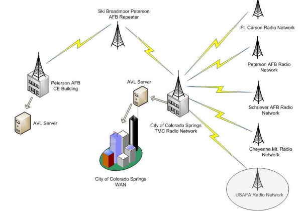
Vehicle location data is transmitted to the Colorado Springs Traffic Management Center (CSTMC) via radio transmission to the radio towers located in downtown Colorado Springs, CO. Data is stored in a central server where various software applications have the capability of deploying the data in a web-based map
Redirection of AVL data from CSTMC Center to Peterson AFB servers under the management of the PAFB Geobase Integration Office and 21st CS. Database server configuration is similar to CSTMC’s with geodatabase architecture used.
AVL tracking data was made available as a web service and stored in and AVL data server for further processing and integration with research applications. As previously mentioned, the USAFA AVL project was a subset of the overall Colorado Springs Automated Vehicle Location system that was designed to address emergency response and preparedness. The configuration of the overall 8 network was centrally located at the CSTMC because it is one of the primary hubs for fiber communication in the city (FIGURE 1). The layout and configuration of data transmission was designed so that the data would be collected on an MS SQL server and then further distributed to other locations such as Peterson AFB and USAFA (FIGURE 2).
| Are you interested in this topic.Then mail to us immediately to get the full report.
email :- contactv2@gmail.com |
